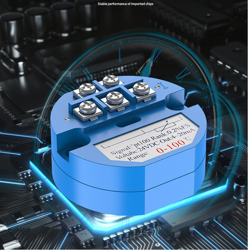
Temperature transmitter module

The temperature transmitter adopts thermocouple and thermal resistance as the temperature measuring element, and the output signal from the temperature measuring element is sent to the transmitter module, after voltage stabilization filtering, operational amplification, nonlinear correction, V/I conversion, constant current and reverse After the protection circuit is processed, it is converted into a 4-20mA current signal 0-5V/0-10V voltage signal which is linearly related to the temperature, and the RS485 digital signal is output.
A device that converts physical measurement signals or ordinary electrical signals into standard electrical signal output or can be output by means of communication protocols. Temperature transmitter is an instrument that converts temperature variables into standardized output signals that can be transmitted, and is mainly used for the measurement and control of temperature parameters in industrial processes. The current transmitter converts the AC current of the main circuit under test into a constant current loop standard signal, which is continuously transmitted to the receiving device.
The temperature current transmitter converts the signal of the temperature sensor into a current signal and connects it to the secondary instrument to display the corresponding temperature. For example, the model of the temperature sensor in the picture is PT100, then the function of the temperature current transmitter is to convert the resistance signal into a current signal, input it to the meter, and display the temperature.
Precautions
The power supply of the temperature transmitter must not have spikes, otherwise the transmitter may be easily damaged. The calibration of the transmitter should be carried out 5 minutes after power-on, and pay attention to the ambient temperature at the time. When measuring high temperature (>>100℃), the sensor cavity and the junction box should be separated by filling materials to prevent the transmitter from being burnt due to the excessive temperature of the junction box. When the sensor is used under severe interference, the housing should be firmly grounded to avoid interference. The power supply and signal output should be transmitted by Ф10 shielded cable, and the crimping nut should be tightened to ensure air tightness. Only the RWB temperature transmitter has a 0~10mA output, which is a three-wire system. Below 5% of the range value, it is not linear due to the off-characteristics of the transistor. The temperature transmitter should be calibrated every 6 months. If the DWB cannot be linearly corrected due to circuit limitations, it is best to select the range according to the instructions to ensure its linearity.
Reasons for inaccurate data display
1. The line is long and the signal is attenuated;
2. The line impedance does not match;
3. The signal is interfered without shielding
Sample Block Quote
Praesent vestibulum congue tellus at fringilla. Curabitur vitae semper sem, eu convallis est. Cras felis nunc commodo loremous convallis vitae interdum non nisl. Maecenas ac est sit amet augue pharetra convallis nec danos.
Sample Paragraph Text
Praesent vestibulum congue tellus at fringilla. Curabitur vitae semper sem, eu convallis est. Cras felis nunc commodo eu convallis vitae interdum non nisl. Maecenas ac est sit amet augue pharetra convallis nec danos dui.
Cras suscipit quam et turpis eleifend vitae malesuada magna congue. Damus id ullamcorper neque. Sed vitae mi a mi pretium aliquet ac sed elitos. Pellentesque nulla eros accumsan quis justo at tincidunt lobortis denimes loremous. Suspendisse vestibulum lectus in lectus volutpat, ut dapibus purus pulvinar. Vestibulum sit amet auctor ipsum.


